Quantcast
Channel: tachometer – Hackaday
Viewing all 32 articles
Browse latest View live

Bluetooth motorcycle control panel with arduino

$
0
0

Motorcycle_in_neutral

[Bill2009] has made some nice progress on a control panel for his motorcycle over at the arduino.cc forums.  It can show speed, tachometer readings for the wheel and engine, as well as indicate the current gear. He reads the square wave coming off of his tachometer input and pulses from a reed switch mounted on the wheel to calculate all this. To top it all off he can monitor the data via a Bluetooth module attached to the board, which is much better than trying to balance a laptop on your knees while cruising down the highway.  He is working on getting the size down so that he can mount the whole assembly inside of his motorcycle. He also plans to add new software features like wind resistance calculations and0 to 60mph timing.


Posted in Arduino Hacks, transportation hacks

CPU tachometer

$
0
0

Recently, analog displays have come back in vogue. This is partially due to the common steam punk theme that is popular right now. [Cristiano] has done an analog display, but instead of brass and polished wood, he’s gone automotive themed with it. He purchased a cheap tachometer from ebay.  A circuit had to be designed to give the tach the signals needed for it to operate, and you can download the schematic from his site. As you can see in the video above, it works well. We think that “shift” light might get annoying pretty quickly.


Posted in peripherals hacks

Adding a tachometer to the SX2 Mini mill

$
0
0

sx2_mill_tach

[Jeff] recently bought an SX2 mini milling machine with plans to eventually automate it for use as a CNC mill. After paying nearly $700 for the mill, he decided there was no way he was willing to pay for the $125 tachometer add on as well. Instead, he reverse-engineered the mill and constructed a tachometer of his own.

He opened the control box and started looking around. After identifying most of the components, he got sidetracked by a 3-pin header that didn’t seem to have any particular function. That is, until he realized that a lathe by the same manufacturer uses the same components, and figured that the header might be used for reversing the motor. Sure enough he was right, and after adding a reverse switch, he got back to business.

He probed the 7-pin socket with his logic analyzer and quickly picked out the mill’s data line. He hooked the line up to an Arduino and in no time had the RPM displayed on an LCD screen.

[Jeff] says that this little experiment is the first of many, since the mill is so hacker friendly. We definitely look forward to seeing a CNC conversion tutorial in the near future.


Filed under: Arduino Hacks, cnc hacks

Digital speedometer with an arduino

$
0
0

[Martyn] is restoring a 32-year-old Honda motorcycle, so when the ancient speedometer broke last year he thought it was prime time to start of a digital speedometer project. We’re loving the results so far, and would love seeing it on a nicely restored bike.

Instead of the relative horror of driving 40 LEDs with a single Arduino, [Martyn] bit the bullet and got a Maxim 7221 LED driver. Controlling 64 LEDs  over a three-wire interface simplified the board design somewhat, allowing [Martyn] to etch his own PCB with the toner transfer & HCl/H2O2 method. To actually power and control the entire circuit, [Martyn] used an Arduino loaded up with a program based  LedControl library makes programming the spedometer a snap.

Although the speedo works, [Martyn] says he isn’t proud of how it looks. We don’t mind – the candy colored jumpers add a nice flair to the project, and they’re hidden behind the face plate of the speedometer. We’re sure once he gets the neutral, high-beam, and warning indicators working with the LED bar array / tachometer, everything will look awesome.

via reddit


Filed under: transportation hacks

Junkyard scavenging nets a tachometer to play with

$
0
0

We never thought to hit the automotive junkyard to find electronics we could play with. But [Istimat] was able to pull this working tachometer from an otherwise destroyed motorcycle dashboard. The Kawasaki part has just three pins on the back of it. By connecting 12V to the IGN pin, ground to GND, and tapping a 12V wire on the unlabeled pin he was able to make the needle dance and knew he was getting somewhere.

His microcontroller of choice for the project is an Arduino board. But the 5V logic levels aren’t going to put out the square wave needed to drive the device. A search of the internet led him to a 2-transistor circuit which lets him get the results seen in the video. His plan is to add functionality that uses the Arduino to pull data in from just about any source and display it on the dial. That computer desk that featured all the CPU load readouts immediately comes to mind.

Do you think the square wave circuit is more complicated than necessary? Could this be done with just one NPN transistor and a pair of resistors?


Filed under: Arduino Hacks

Arduino Tachometer tutorial

$
0
0

This tutorial will guide you through the process of building a tachometer around an Arduino. Tachometers are used to measure rotation rate in Revolutions Per Minute (RPM). You don’t need much in the way of hardware, this version uses an Infrared beam to measure fan speed. As with last year’s PIC-based tutorial, [Chris] is using a character LCD to output the reading. Wiring and driving the LCD ends up being the hardest part.

An IR transmitter/receiver pair are positioned on either side of the fan. When the blade passes in between then, the receiver shuts off a transistor connected to one of the Arduino’s external interrupt pins. He shows how to use this interrupt to measure the amount of time between the passing of each fan blade. If you divide for the number of blades, and average the reading for greater accuracy, you can easily calculate RPM.

Another alternative would have been to use a reflectance sensor which allows to for the transmitter and receiver to both be on the same side of the fan.


Filed under: Arduino Hacks

Sound Card Tachometer Rises From the Junkbox

$
0
0

sound-tach

We love writing up projects that re-use lots of old parts. In fact, we save the links and use them as defense when our significant other complains about the “junk” in the basement. No, that tactic hasn’t ever worked, but we’re going to keep trying. Case in point, [Wotboa] needed a non-contact tachometer. There are plenty of commercial products which do just that. After consulting his parts bin, [wotboa] realized he had everything he needed to hack out his own. An IR break beam sensor from an old printer was a perfect fit in an aluminum tube. With the outer shell removed, the emitter and detector were mounted in the nylon shell of an old PC power supply connector, effectively turning them pair into a reflective sensor. To amplify the circuit, [wotboa] used a simple 2n2222 transistor circuit. The key is to keep the voltage seen by the sound card the range of a line level signal. This was accomplished by adding a 2.2 Megohm resistor in line with the output. [wotboa] drew his schematic in eagle, and etched his own PCB for the project. Even the tachometer’s case came from the parts bin. An old wall wart power supply gave up its shell for the cause, though [wotboa] is saving the transformer for another project.

For sensing, [wotba] used [Christian Zeitnitz's] Soundcard Oscilloscope software.  Measuring the RPM of the device under test is simply a matter of determining the frequency of the signal and multiplying by 60. A 400 Hz signal would correspond to a shaft turning at 24,000 RPM. The circuit performs well in the range of RPM [wotboa] needs, but using a sound card does have its limits. The signals on the scope look a bit distorted from the square waves one would expect. This is due to the AC coupled nature of sound cards. As the signal approaches DC, the waveform will become more distorted. One possible fix for this would be to remove the AC coupling capacitor on the sound card’s input. With the capacitor removed, an op amp buffer would be a good idea to prevent damage to the sound card.

[Via Instructables]


Filed under: misc hacks

Visualize Vroom with This RGB LED Tachometer

$
0
0

tach[Pete Mills] recently bought the all-new Ford Fiesta, which offers impressive fuel economy over that of his Jeep. He soon figured out that he has real time access to a wealth of engine and chassis data through Ford’s OpenXC platform and used it to build blueShift, a neopixel tachometer. The car already has a tach, but this one is more visual, can be seen in periphery, and is just plain fun.

In case you hadn’t heard, the OpenXC platform is Ford’s consumer key to the kingdom of OBD2 treasures. It unlocks the magic through its Vehicle Interface, which plugs into the OBD2 port and translates the CAN bus messages to OpenXC format. These messages are packaged into JSON format and can be sent over Bluetooth or Ethernet/Wi-Fi to an Android, Python, or iOS device.

[Pete] went with Bluetooth and used a BlueSMiRF with an Arduino Pro Mini. He derives power from the car’s on-board USB port, but has future plans to use the OpenXC VI port. blueShift reads the RPM data and displays a green trail as the engine revs up. At the peak revolution, it shows a red LED. This one is sticky and will persist for the lesser of three seconds or the time elapsed to a new positive RPM. [Pete] is also reading the headlight status of the car. As soon as they come on, the RGB LEDs dim to avoid blinding him at night.

[Pete] wanted to make an enclosure more finished-looking than a Tupperware box. He nearly detoured into 3D-printer design, but ended up putting together a Prusa i3v and came up with this RAM mount-compatible enclosure. His fantastic write-up and code are on his blog, but you can make the jump to see a short demo and a full explanation video. You can also make smart brake lights or even create art with OpenXC.

Demo video of blueShift:

Full explanation:


Filed under: Arduino Hacks, car hacks

Fantastic Tach Is Strangely Called Tachtastic

$
0
0

tachtastic diy tachometer

We all have projects from yesteryear that we wish had been documented better. [EjaadTech] is fighting back by creating a project page about a tachometer he built 3 years ago while in college. He’s done a great write-up documenting all the steps from bread-boarding to testing to finished project. All of the code necessary for this tachometer is available too, just in case you’d like to make one yourself.

At the heart of the project is an AVR ATMega8 chip that performs the calculations and controls the LCD output screen that displays both the immediate RPM as well as the average. To hold everything together, [EjaadTech] etched his own custom PCB board that we must say looks pretty good. In addition to holding all the necessary components, there is also an ISP connector for programming and re-programming.

There are two attachment options for sensing the RPM. One is a beam-break style where the IR emitter is on one side of the object and the receiver is on the other. This type of sensor would work well with something like a fan, where the blades would break the IR beam as they passed by. Then other attachment has the IR emitter and receiver on one board mounted next to each other. The emitter continually sends out a signal and the receiver counts how often it sees a reflection. This works for rotating objects such as shafts where there would not be a regular break in the IR beam. For this reflective-based setup to work there would have to be a small piece of reflective tape on the shaft providing a once-per-revolution reflection point. Notice the use of female headers to block any stray IR beams from causing an inaccurate reading… simple and effective.


Filed under: Microcontrollers

Redlining Your CPU via Automotive Tachometer

$
0
0

Many CPU-usage widgets have stylistically borrowed from vehicles, displaying something mimicking the tachometer found in the dashboard. [Pat] took it a step further and tried his hand at re-borrowing this style. He figured, why not use an actual physical tachometer to display how hard the CPU on his Raspberry Pi was revving?

With the goal of tuning 0-100% CPU usage to 0-8000 RPM on the tach, the first step was diagnosing the range of PWM input frequencies that moved the needle across the tach’s full arc. Using his Tektronix 3252C function generator he quickly determined 0-440 Hz would be needed and graphed a handful of intermediate points. The response curve was not linear, so he drew up some fudging guidelines to make all the datapoints match.

Next, he wrote a few lines of Python (he shared) to make the Pi to poll its CPU usage and translate it to the proper frequency. The Pi makes outputting easy, GPIO pin 11 carried the signal to a 7404 for buffering, then out to the tach. The automotive tach itself ran on 12V, but its input signal required only 5V so he pulled a 7805 from his parts bin.

Once it was all put together it worked beautifully using just the one extra component. Some might see this as more clever than USB dependent or Arduino bloated based tachometer hacks.

See the video after the break of the tach twitching even when the mouse moved, and pegging the red when opening a browser. No more need to use up valuable screen real-estate (or use a screen at all) if you want to see at a glance when your Pi is putting in work.

If you were hoping for a device that adds a tachometer to display actual RPMs of something, we have covered that before too!


Filed under: car hacks, Raspberry Pi

Excuse me, Sir. Do you know how fast your Lathe was traveling back there?

$
0
0

When machining metal, it is important to know how fast the cutting tool is traveling in relation to the surface of the part being machined. This amount is called the ‘Surface Speed’. There are Surface Speed standards for cutting different types of materials and it is good practice to stick with those standards in order to end up with a good surface finish as well as maximizing tool life. On a lathe, for example, having a known target Surface Speed in mind as well as a part finish diameter, it is possible to calculate the necessary spindle speed.

Hobbyist [Paul] wanted a method of measuring his lathe’s spindle speed. Since spindle speed is measured in RPM, it made complete sense to install a tachometer. After browsing eBay for a bit he found one for about $20. His purchase came with the numeric LED display, a mounting bezel and the all important hall effect sensor. The Hall effect sensor measures changes in a magnetic field and in turn varies its output voltage. [Paul] fabbed up an aluminum bracket that supports the sensor just off of the rear of the lathe spindle. A magnet was then glued to the outside diameter of the spindle below the sensor. The once per revolution signal is generated every time the magnet passes the sensor while the lathe is running. The display was mounted to the lathe near eye height by means of another aluminum bracket and case.

After a little work, [Paul] can now keep a close eye on his spindle speed with a quick glance over at his new tachometer display while he’s turning those perfect parts! If this project tickles your fancy, you may want to check out this fantastic DIY tachometer or this one that uses a soundcard.


Filed under: tool hacks

2D Printed Tachometer For A Lathe

$
0
0

If you ever wanted a reason to have DC lighting pointed at the spinny part of your mill and lathe, [Bill] tells a great story. One day, he noticed the teeth on his lathe chuck would change color – red, then blue, then red. His conclusion was the fluorescent lights above his workbench was flashing, as fluorescent lights normally do.

Imagine if the teeth on [Bill]’s chuck weren’t painted. They would appear stationary. That’s usually a bad thing when one of the risks of using a lathe is ‘descalping.’ Buy an LED or incandescent work light for your shop.

This unique effect of blinking lights got [Bill] thinking, though. Could these fluorescent lights be used as a strobe light? Could it measure the RPM of the lathe?

And so began [Bill]’s quest for a 2D printed lathe tachometer. The first attempt was to wrap a piece of paper printed with evenly space numbers around the chuck. This did not work. The flash from his fluorescent bulb was too long, and the numbers were just a blur. He moved on to a maximum-contrast pattern those of us who had a ‘DJ phase’ might recognize immediately.

By printing out a piece of paper with alternating black and white bands, [Bill] was able to read off the RPM of his chuck with ease. That’s after he realized fluorescent lights blink twice per cycle, or 120 times a second. If you have a 3″ mini-lathe, [Bill] put the relevant files up, ready to be taped to a chuck.


Filed under: tool hacks

Instrument Cluster Clock Gets The Show On The Road

$
0
0

While driving around one day, [Esko] noticed that the numbers and dials on a speedometer would be a pretty great medium for a clock build. This was his first project using a microcontroller, and with no time to lose he got his hands on the instrument cluster from a Fiat and used it to make a very unique timepiece.

The instrument cluster he chose was from a diesel Fiat Stilo, which [Esko] chose because the tachometer on the diesel version suited his timekeeping needs almost exactly. The speedometer measures almost all the way to 240 kph which works well for a 24-hour clock too. With the major part sourced, he found an Arduino clone and hit the road (figuratively speaking). A major focus of this project was getting the CAN bus signals sorted out. It helped that the Arduino clone he found had this functionality built-in (and ended up being cheaper than a real Arduino and shield) but he still had quite a bit of difficulty figuring out all of the signals.

In the end he got everything working, using a built-in servo motor in the cluster to make a “ticking” sound for seconds, and using the fuel gauge to keep track of the minutes. [Esko] also donated it to a local car museum when he finished so that others can enjoy this unique timepiece. Be sure to check out the video below to see this clock in action, and if you’re looking for other uses for instrument clusters that you might have lying around, be sure to check out this cluster used for video games.

The mechanics in dashboards are awesome, and produced at scale. That’s why our own [Adam Fabio] is able to get a hold of that type of hardware for his Analog Gauge Stepper kit. He simply adds a 3D printed needle, and a PCB to make interfacing easy.


Filed under: car hacks, clock hacks

Analog Guts Display GPS Velocity in this Hybrid Speedometer

$
0
0

A digital dash is cool and all, but analog gauges have lasting appeal. There’s something about the simplicity of a purely mechanical gauge connected directly to a vehicle’s transmission. Of course that’s not what’s hapenning here. Instead, this build is an analog display for GPS-acquired speed data.

The video below does a good job at explaining the basics of [Grant Stephens]’ build. The display itself is a gutted marine speedometer fitted with the movement from a motorcycle tachometer. The tach was designed to take a 4-volt peak-to-peak square wave input signal, the frequency of which is proportional to engine speed. To display road speed, [Grant] stuffed an ATTiny85 with a GPS module into the gauge and cooked up a script to convert the GPS velocity data into a square wave. There’s obviously some latency, and the gauge doesn’t appear to register low speeds very well, but all in all it seems to match up well to the stock speedo once you convert to metric.

There’s plenty of room for improvement, but we can see other applications where an analog representation of GPS data could be useful. And analog gauges are just plain fun to digitize – like these old meters and gauges used to display web-scraped weather data.


Filed under: car hacks, gps hacks

Quick Arduino Hack Lets Tach-less Car Display Shift Points

$
0
0

A tachometer used to be an accessory added to the dash of only the sportiest of cars, but now they’re pretty much standard equipment on everything from sleek coupes to the family truckster. If your daily driver was born without a tach, fear not – a simple Arduino tachometer is well within your reach.

The tach-less vehicle in question is [deepsyx]’s Opel Astra, which from the video below seems to have the pep and manual transmission that would make a tach especially useful. Eschewing the traditional analog meter display or even a digital readout, [deepsyx] opted to indicate shift points with four LEDs mounted to a scrap of old credit card. The first LED lights at 4000 RPM, with subsequent LEDs coming on at each 500 RPM increase beyond that. At 5800 RPM, all the LEDs blink as a redline warning.  [Deepsyx] even provides a serial output of the smoothed RPM value, so logging of RPM data is a possible future enhancement.

The project is sensing engine speed using the coil trigger signal – a signal sent from the Engine Control Unit (ECU) which tells one of the ignition coilpacks to fire. The high voltage signal from the coilpack passes on to the spark plug, which ignites the air-fuel mixture in that cylinder. This is a good way to determine engine RPM without mechanical modifications to the car. Just make sure you modify the code for the correct number of cylinders in your vehicle.

Simple, cheap, effective – even if it is more of a shift point indicator than true tachometer, it gets the job done. But if you’re looking for a more traditional display and have a more recent vintage car, this sweeping LED tachometer might suit you more.

[via r/Arduino]


Filed under: Arduino Hacks, transportation hacks

How To Use a Photo Tachometer

$
0
0

If you’re into anything even vaguely mechanical on the broad hacking spectrum, you’ve come into contact with things that spin. Sometimes, it’s important to know precisely how fast they are spinning! When you’ve got the need to know angular speed, you need a device to measure it. That device is a tachometer. And the most useful tachometer is the non-contact photo-tachometer.


The basic principle of operation of a photo-tachometer is quite simple. The device contains a light source – typically a laser, which can create a focused, coherent beam of light. This beam of light is capable of bouncing off of reflective objects.

To use the photo tachometer, you start by creating a reflective mark on the rotating surface you wish to measure. You must also ensure the rest of the rotating surface is comparatively non-reflective. An easy way to do this would be to create a white spot with a paint marker on an otherwise black or dull-metal shaft. Then, aim the beam of light from the photo-tachometer at the mark on the spinning shaft. Each time the reflective spot passes the beam of the photo-tachometer, some light is reflected back towards the device, where it is picked up by a light sensor. By counting the number of times the light sensor is triggered in a given time, it’s possible to determine the rotational speed of the machinery under test.

For example, let’s say we have a motor spinning at 1200 revolutions per minute. We aim the photo-tachometer’s beam at the white spot we’ve marked on the motor’s shaft. Let’s assume the photo-tachometer counts the number of pulses it sees in a unit time of one second to make its measurements. In one second, the white spot will pass the beam twenty times, triggering our light sensor as it goes by. The microcontroller in the photo-tachometer then does some simple maths – twenty pulses in one second, multiplied by 60 seconds – and we get a rotational speed of 1200 revolutions per minute on the display.

It is easy to imagine that if our shaft is rotating much more slowly, on the order of 10 RPM, our photo-tachometer will only see one pulse every six seconds. If we up this to 12 RPM, it’s still only one pulse every five seconds. Our tach is going to suffer trying to measure such low rotational speeds and it’s going to take a long time for it to notice any changes. Is there anything we can do to help in this situation?

Why yes, there is! We can place additional reflective spots on our rotating shaft. Let’s put ten spots on our rotating motor shaft. Now at 10 RPM, we’re getting a pulse of light every 0.6 seconds, and at 12 RPM, every 0.5 seconds. Our tach is now able to much more quickly respond to changes in speed at the low range – and we just need to remember to divide the display speed by ten to account for our additional markers.
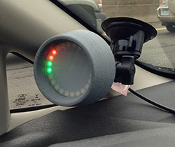
There are other tricks you can use to improve performance, too. Many photo-tachs come with a supply of retro-reflective tape in the box. This is a special tape filled with lots of microscopic glass spheres that allow the tape to reflect light at any angle. Using this instead of white paint on a rotating machine allows us to measure with the photo-tachometer at an angle other than perpendicular to the marking. I used this myself to make a measurement of my car’s engine speed. It was impossible to point the tachometer straight at the crankshaft – but with the retro-reflective tape, I was able to point the laser at the crank pulley from above at an odd angle and still get a good reading.

The real power of photo-tachometers is they make it easy to get accurate rotational speed measurements without having to make any major modifications to the machinery beyond a spot of paint or tape. It’s a great non-contact method of measurement, and a usable photo-tach can be had for under $20 on eBay. I’ve wrapped up a review of the DT2234C+ tachometer on YouTube for your consideration. It’s the kind of thing that you’ll find incredibly useful having stashed away in the back of your toolbox. You’ll never know when you need it!


Filed under: Engineering, Hackaday Columns

Art With Steppers And STM32

$
0
0

Automotive dashboards are something that largely go untouched in the average car’s life. Other than the occasional wipe with a damp cloth, they’re generally reliable for the life of the car and considered too tricky to repair as age sets in. Nevertheless, some hackers find themselves tinkering with them, and learn skills in the process, such as how to control stepper motors and talk to the CAN bus. Having done some projects in the past, [Dan] had some old tachometers lying around and decided to turn them into a piece of art.

The build is powered by an STM32 – a powerful ARM-based platform with plenty of IO and potential. [Dan] leveraged its capabilities to have the board generate music and react to its onboard accelerometer data while also driving the stepper motors from the old tachometers. The project was then completed by 3D printing a mounting plate and placing the tachometer assemblies into the back of an IKEA canvas print.

The end result is a piece of wall art that emits eerie stringed music while twitching around. It came about from [Dan]’s prior projects in working with dashboards. It’s a fun use of some well-earned hacking skills, but we reckon there’s even more potential. There’s a huge number of projects that could benefit from lightweight tiny actuators, and we’d love to see a robot made entirely out of junkyard dashboard parts.

For another dashboard hack, why not check out this beautiful Jeep desk clock?


Filed under: classic hacks

Nixie Tachometer Displays in Style

$
0
0

Nixietach II is a feature-rich tachomoter [Jeff LaBundy] built for his 1971 Ford LTD. It displays RPM with an error rate of only 0.03 RPM at 1,000 RPM

The latest iteration of a long-running project, [Jeff] approached it with three goals: the tachometer had to be self-contained and easy to install, the enclosure had to be of reasonable size, and it had to include new and exciting features over the first two versions.

The finished project consists of an enclosure mounted under the dash with a sensor box in the engine bay connected to the ignition coil. He can also flip a switch and the Nixietach serves as a dwell sensor able to measure the cam’s angle of rotation during which the ignition system’s contact points are closed.  The dash-mounted display consists of those awesome Soviet nixie tubes with a lovely screen-printed case. Its reverse has a USB plug for datalogging and a programming interface.

Hackaday has published some great car projects recently, like this chess set built from car parts and a 90-degree gearbox harvested from a wrecked car.


Filed under: car hacks

The Tachometer Inside Your Smartphone

$
0
0

It’s the latest in instrumentation for the well-appointed shop — an acoustically coupled fast Fourier transform tachometer. Sounds expensive, but it’s really just using a smartphone spectrum analyzer app to indirectly measure tool speeds. And it looks like it could be incredibly handy.

Normally, non-contact tachometers are optically coupled, using photoreceptors to measure light flashing off of a shaft or a tool. But that requires a clear view of the machine, often putting hands far too close to the danger zone. [Matthias Wandel]’s method doesn’t require line of sight because it relies on a cheap spectrum analyzer app to listen to a machine’s sound. The software displays peaks at various frequencies, and with a little analysis and some simple math, the shaft speed of the machine can be determined. [Matthias] explains how to exclude harmonics, where to find power line hum, isolating commutator artifacts, and how to do all the calculations. You’ll need to know a little about your tooling to get the right RPM, and obviously you’ll be limited by the audio frequency response of your phone or tablet. But we think this is a great tip.

[Matthias] is no stranger to shop innovations and putting technology to work in simple but elegant ways. We wonder if spectrum analysis could be used to find harmonics and help with his vibration damping solution for a contractor table saw.

Thanks to [Itay Ramot] for the tip.

Tachometer Uses Light, Arduinos

$
0
0

To measure how fast something spins, most of us will reach for a tachometer without thinking much about how it works. Tachometers are often found in cars to measure engine RPM, but handheld units can be used for measuring the speed of rotation for other things as well. While some have mechanical shafts that must make physical contact with whatever you’re trying to measure, [electronoobs] has created a contactless tachometer that uses infrared light to take RPM measurements instead.

The tool uses an infrared emitter/detector pair along with an op amp to sense revolution speed. The signal from the IR detector is passed through an op amp in order to improve the quality of the signal and then that is fed into an Arduino. The device also features an OLED screen and a fine-tuning potentiometer all within its own self-contained, 3D-printed case and is powered by a 9 V battery, and can measure up to 10,000 RPM.

The only downside to this design is that a piece of white tape needs to be applied to the subject in order to get the IR detector to work properly, but this is an acceptable tradeoff for not having to make physical contact with a high-speed rotating shaft. All of the schematics and G code are available on the project site too if you want to build your own, and if you’re curious as to what other tools Arduinos have been used in be sure to check out the Arduino-based precision jig.

Viewing all 32 articles
Browse latest View live


<script src="https://jsc.adskeeper.com/r/s/rssing.com.1596347.js" async> </script>